Hexapod H1
This is the second working hexapod robot I have ever built, and the first one that I decided to make open-source. As shown in the comparison below, I completely re-designed the physical structure of the robot from the prototype version and managed to:
- Shrink the size down to half of my prototype version.
- Designed a printed circuit board to improve wire management.
- Reduced the number of screws needed to assemble the robot, and added other features.
Building hexapod H1 helped me practice how to think as a user of my "product" while performing engineering design. Though it still has so much room for improvements, I am satisfied with what I accomplished and have enjoyed every bit of the process.
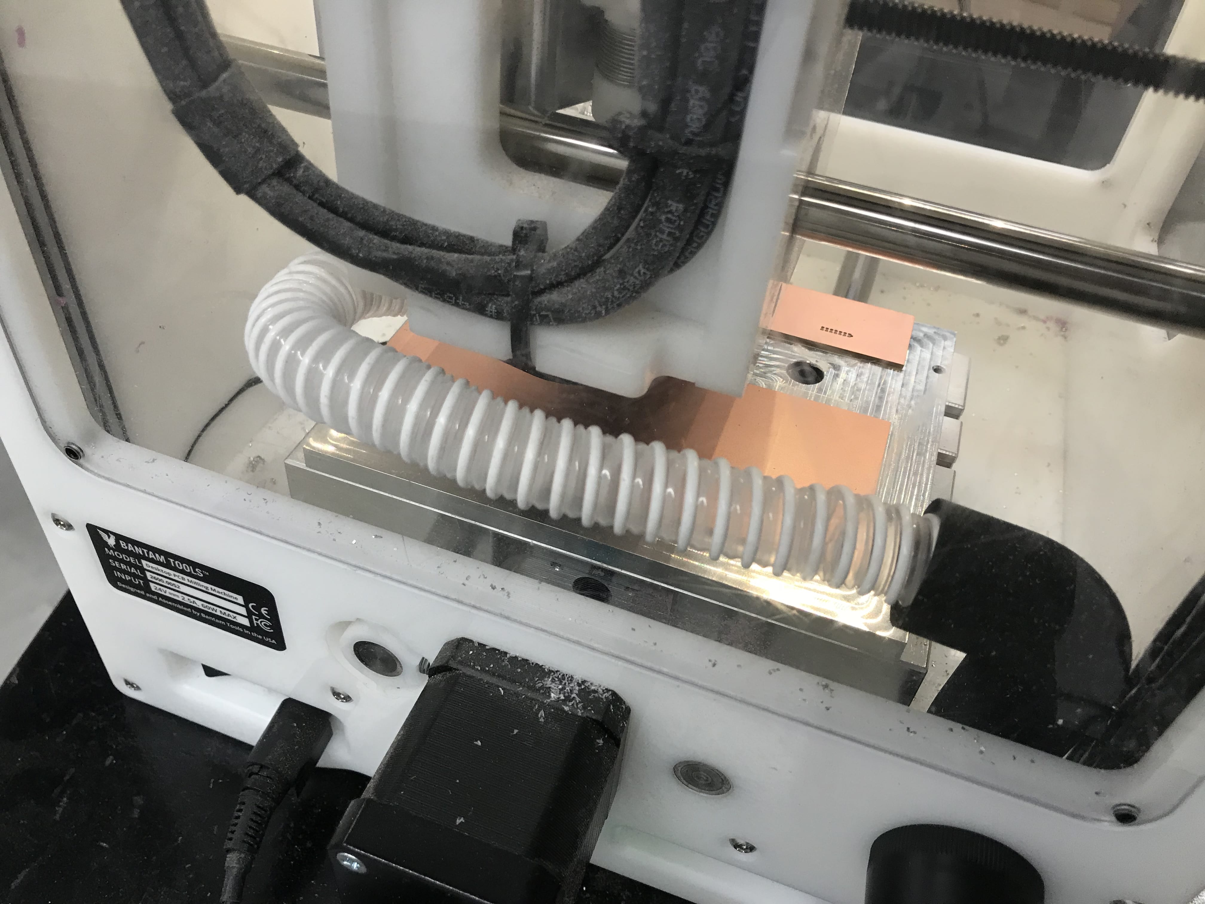
The robot consists of 12 MG90S metal servos. It runs with an Adafruit Feather Hazzah and the PCA9685 servo driver, and is controlled over Wifi by running a small server in a shared network. The legs were 3D printed with a Prusia MK3S in PLA. Click here for the CAD models and here for my code.

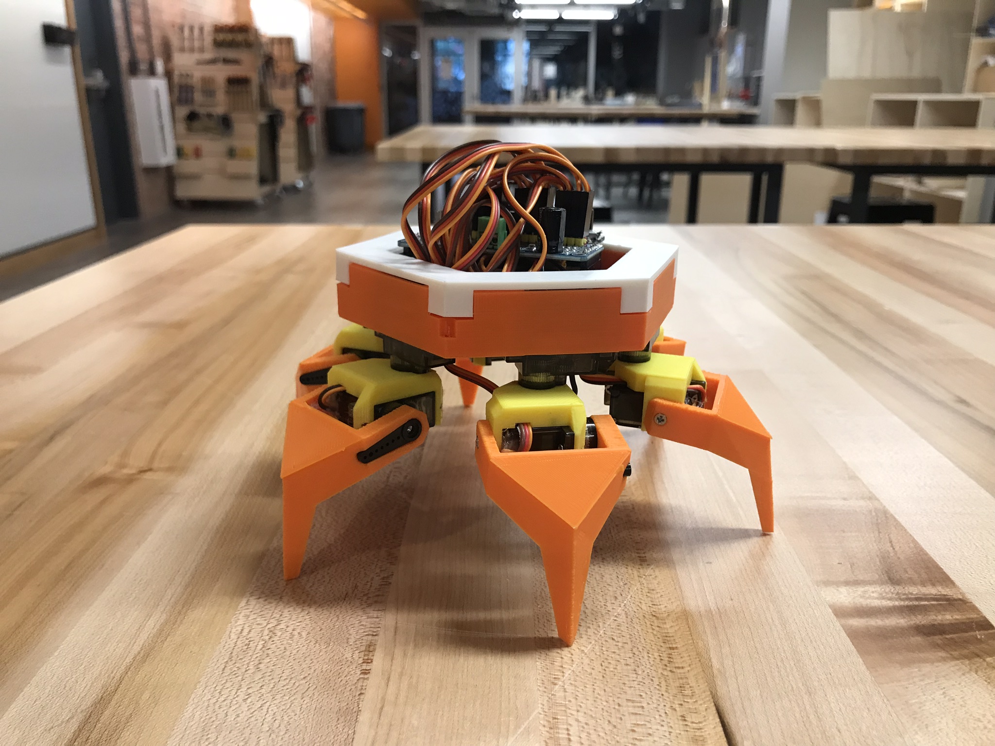
Robot in Action
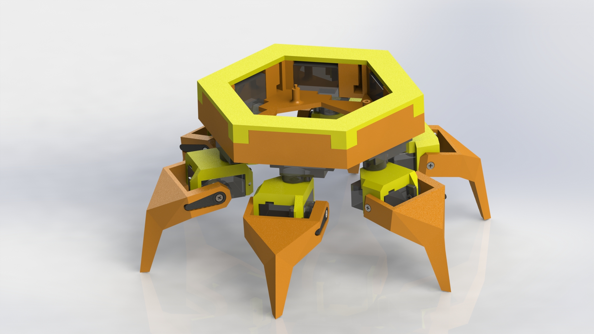
A Closer Look
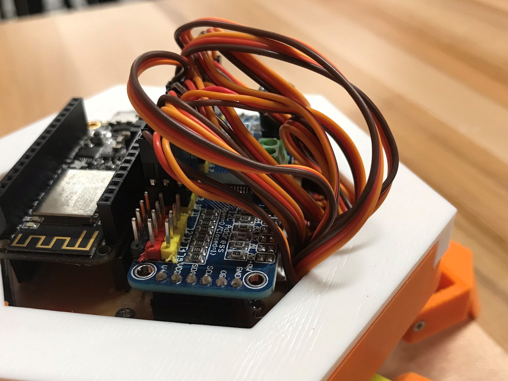
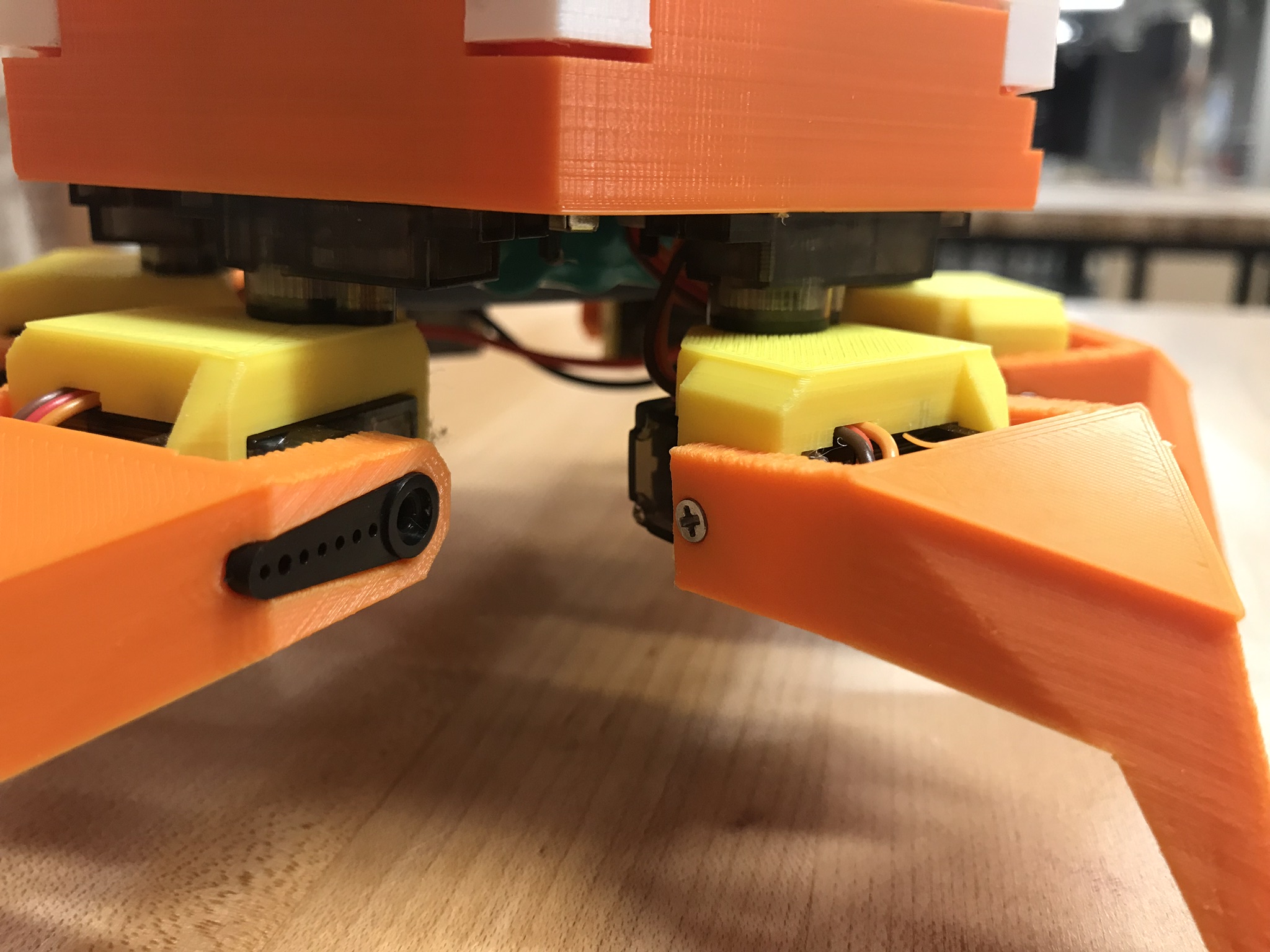
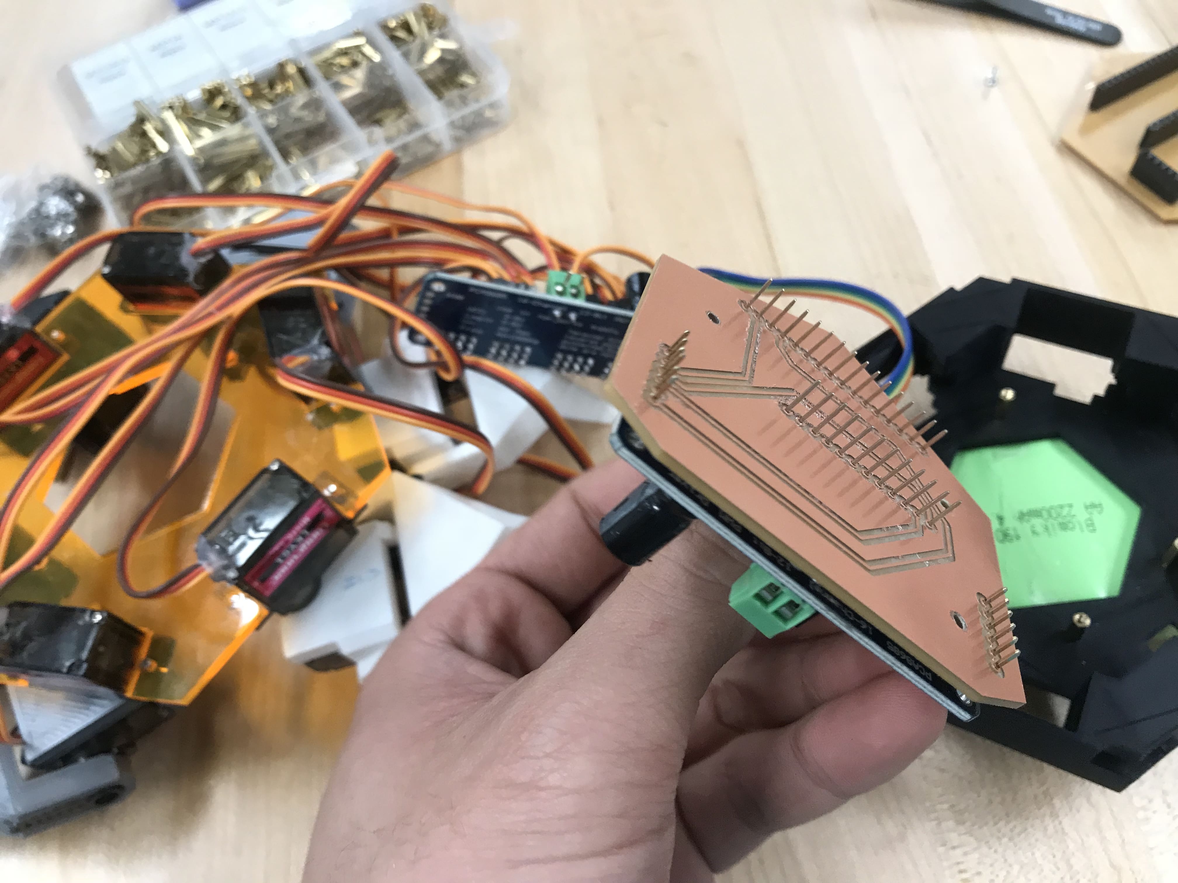
In order to reduce the size of the robot while using the same hardware components, I moved the leg servos underneath the top servos. Fore wire management, I designed a simple PCB, which simply connects the battery, the microcontroller, and the servo driver board. This helped me get rid of the dangling jumper wires and breadboard, enabling me to then fit all the electronics within the main body of the robot. I also added a extended pcb structure (shown in the sketches later), which hosts the switches for the logic and servo power inputs.


In the new 3D-modeled leg and middle components, I incorporated the profile of the servo horns. This allows me to mount the 3D printed parts directly to servos without the need to use a screw.

Building Process

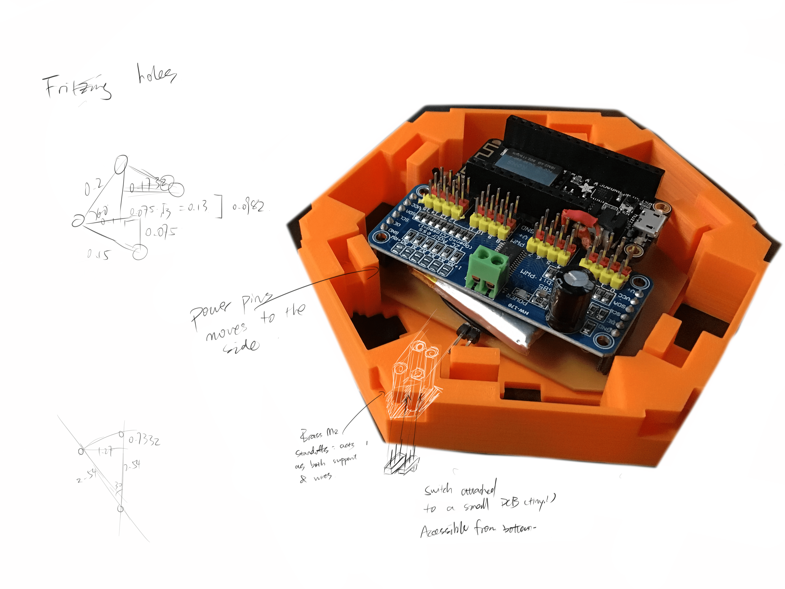
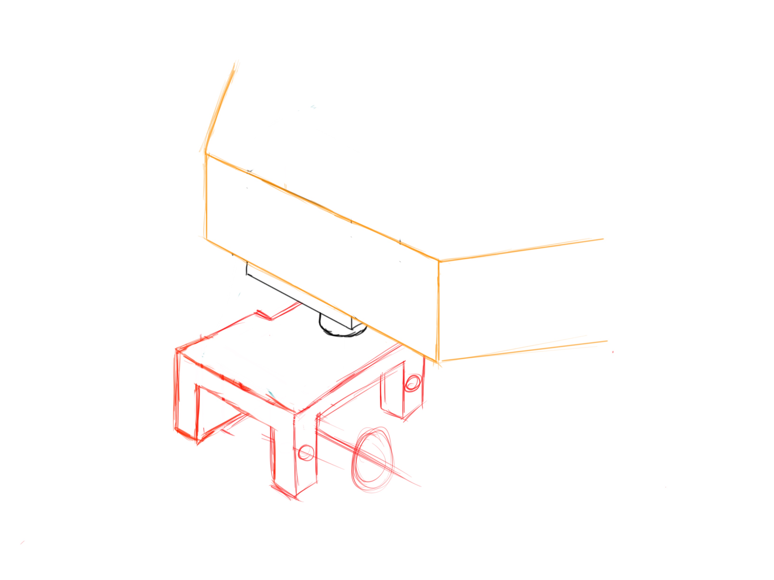
Sketching and CADing
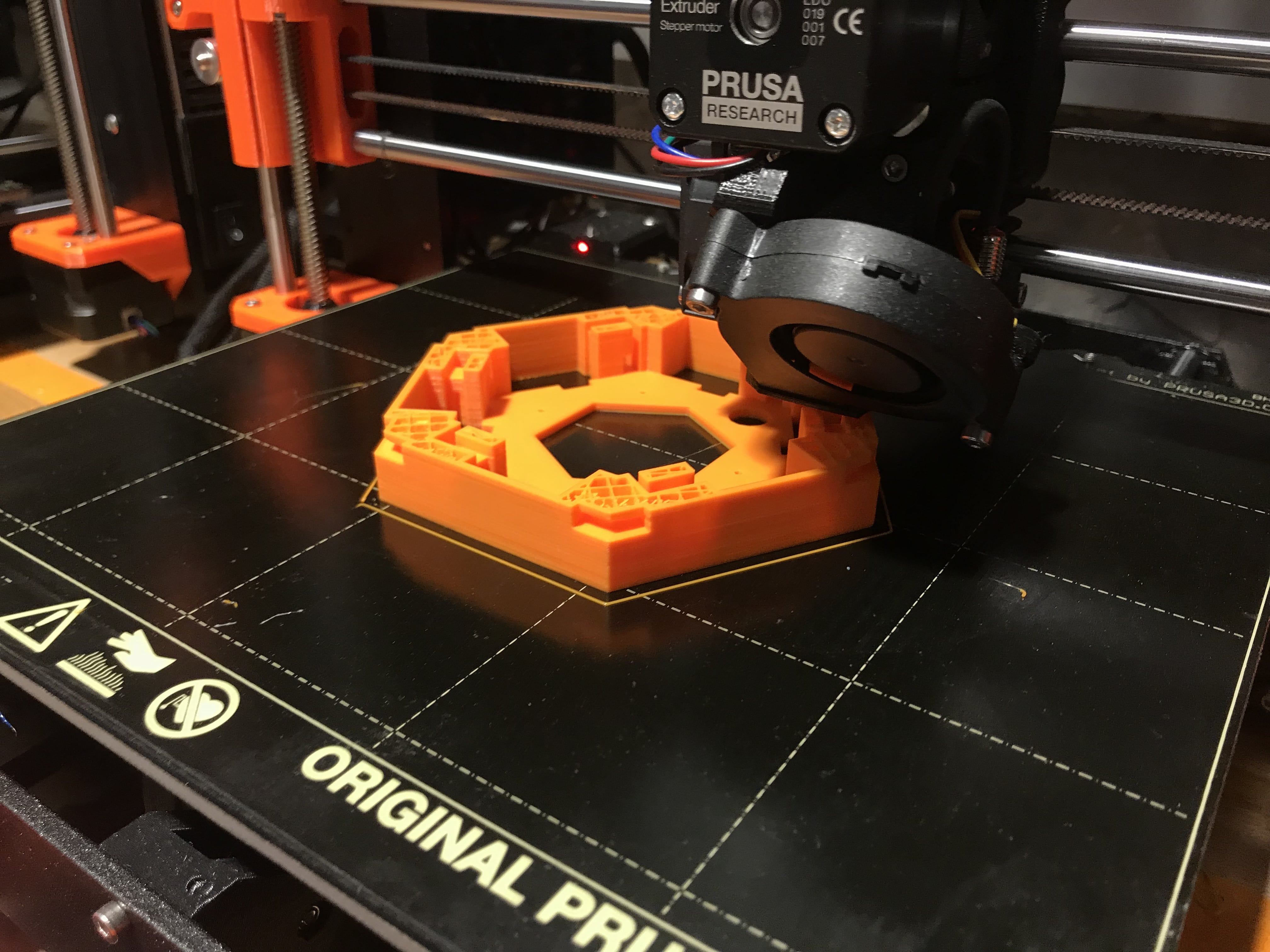
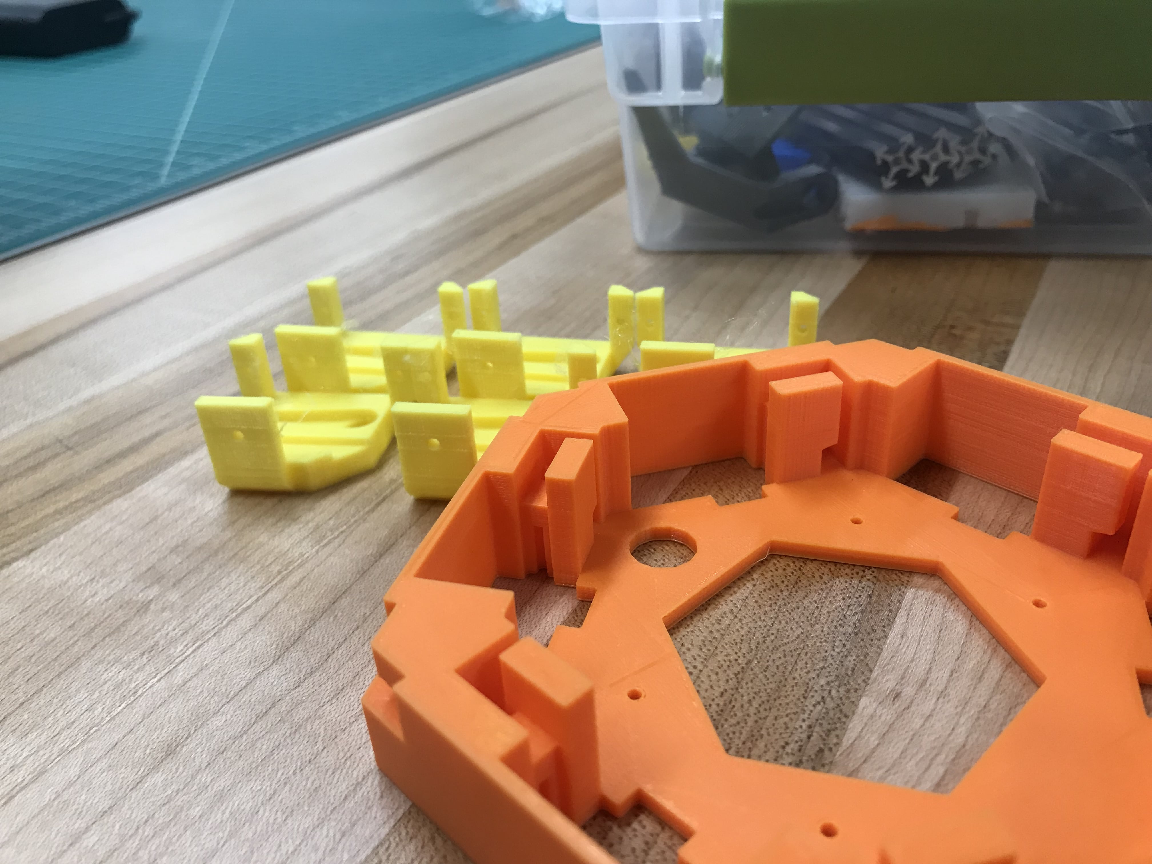
Prototyping and Testing