Six Feet Tall
In the fall of 2019, the professor who worked with me on the small ceramics printer got a grant for us from her department to build a large-scale 3D printer for ceramics and various other types of materials that can be made into a consistent paste form (take paper pule as an example). With the experience I gained from working on the small printer, I came up with a design mostly from scratch, with some inspiration drown from some pre-existing ceramics 3D printers (mainly the printers from WASP). With a bill of materials, we ordered some essential parts and started building version 1. I also invited Jacob Sorscher E'21, a friend of mine who is also a mechanical engineering major, to join the team.
Latest Update
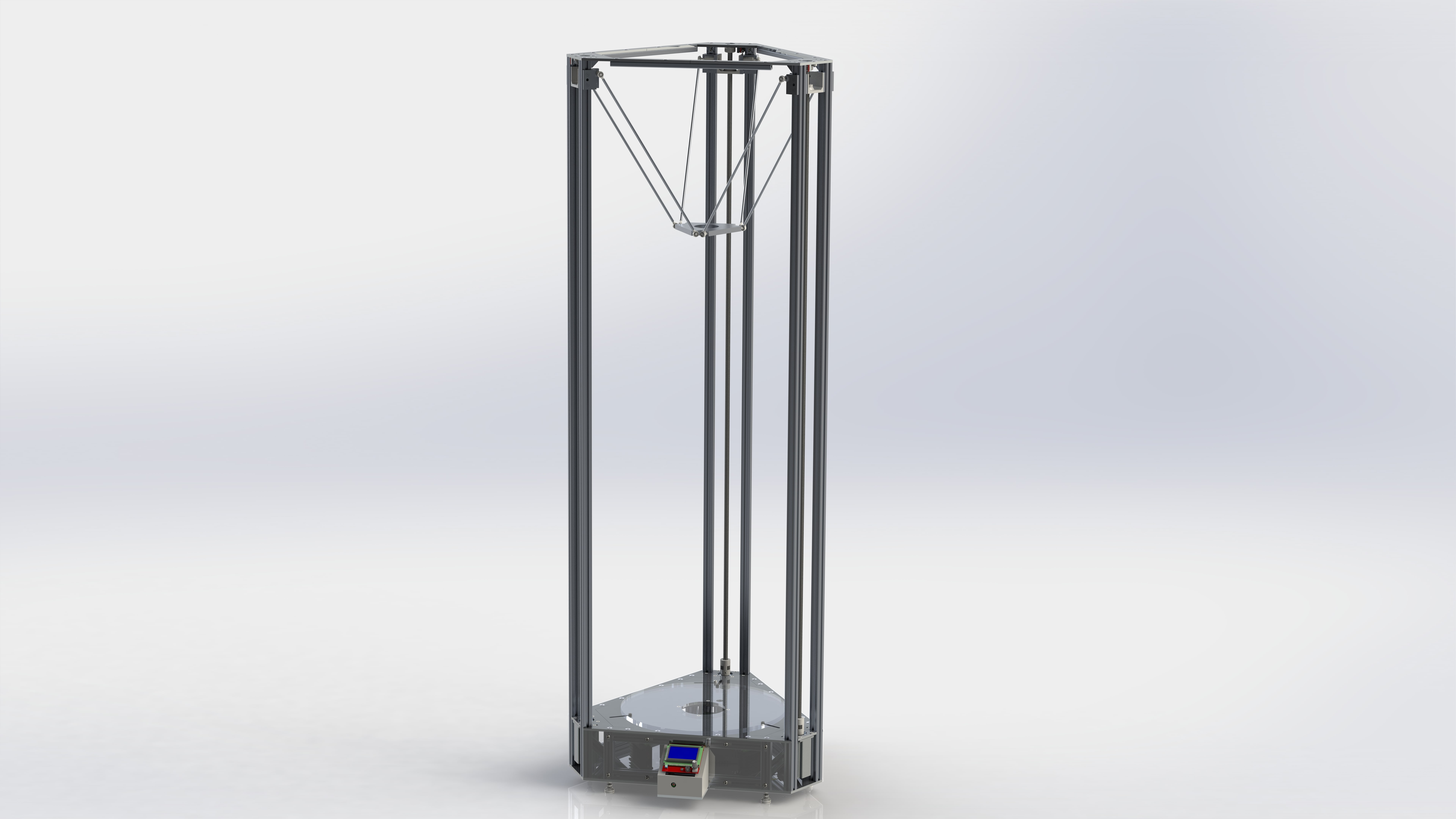
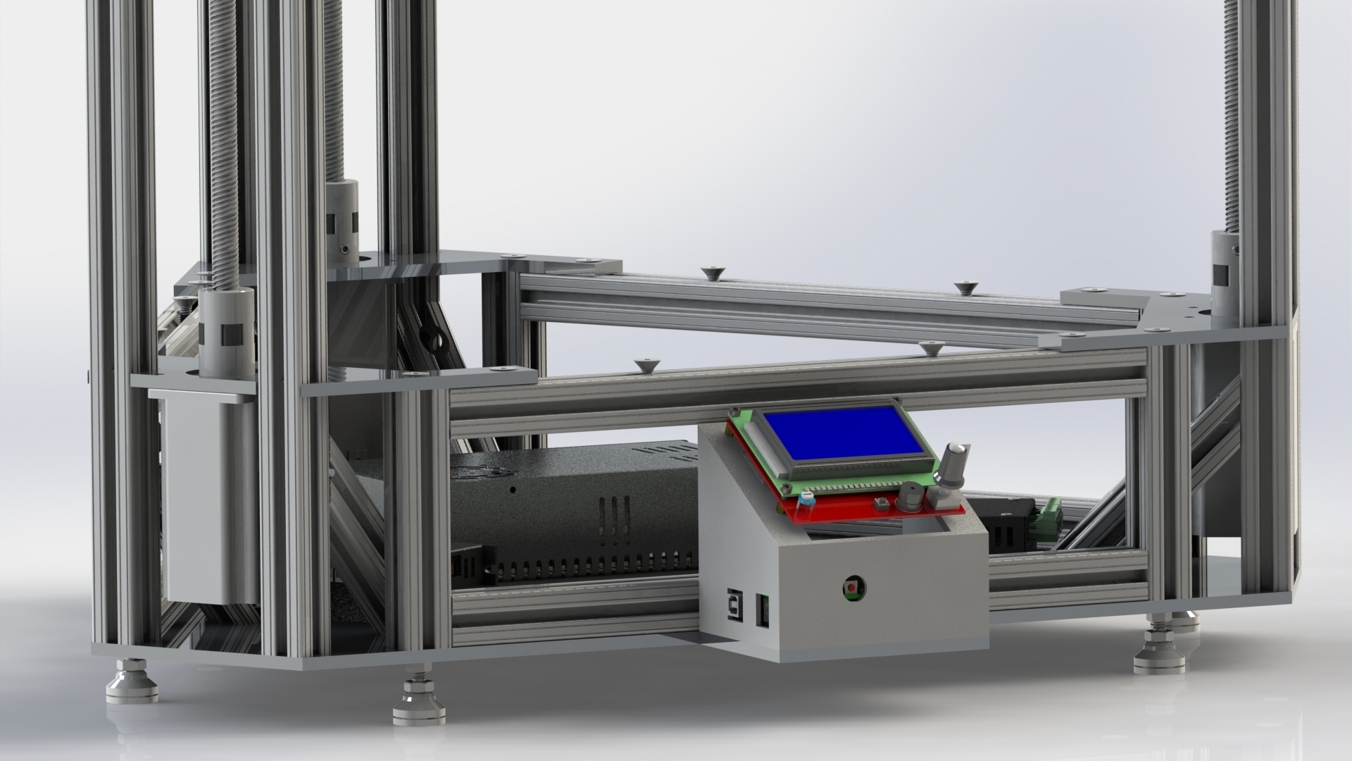
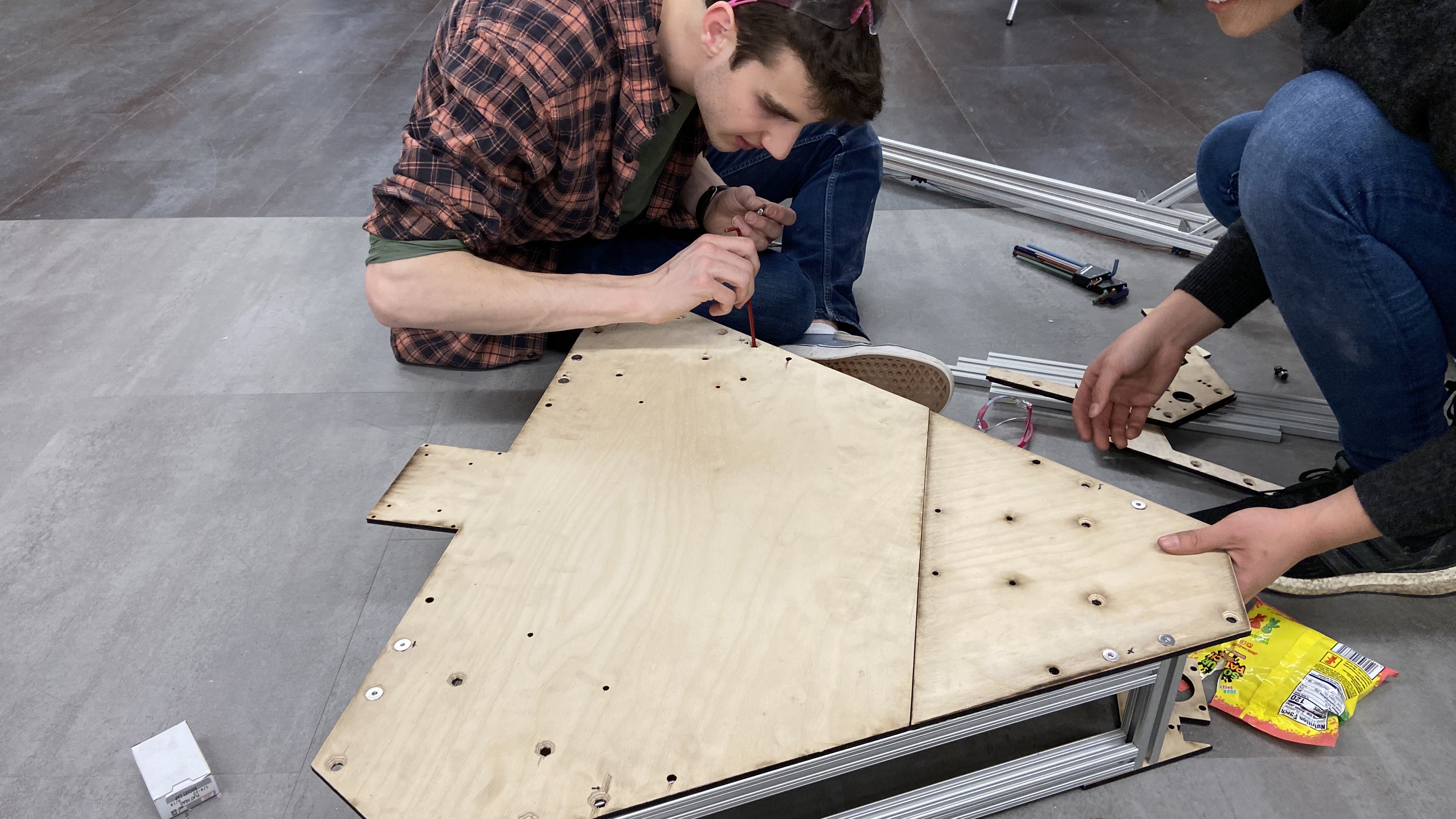
We have successfully assembled the main structure for the first time. We have not yet placed the orders for the aluminum plates, and are substituting the aluminum plates with laser-cut plywood of the same thickness as temporary placeholders. This way we can double-check to make sure that the design does not have any major flaws when we place the big money order for custom fabrication.

What the printer looks like in March 2020 right before school closed due to pandemic
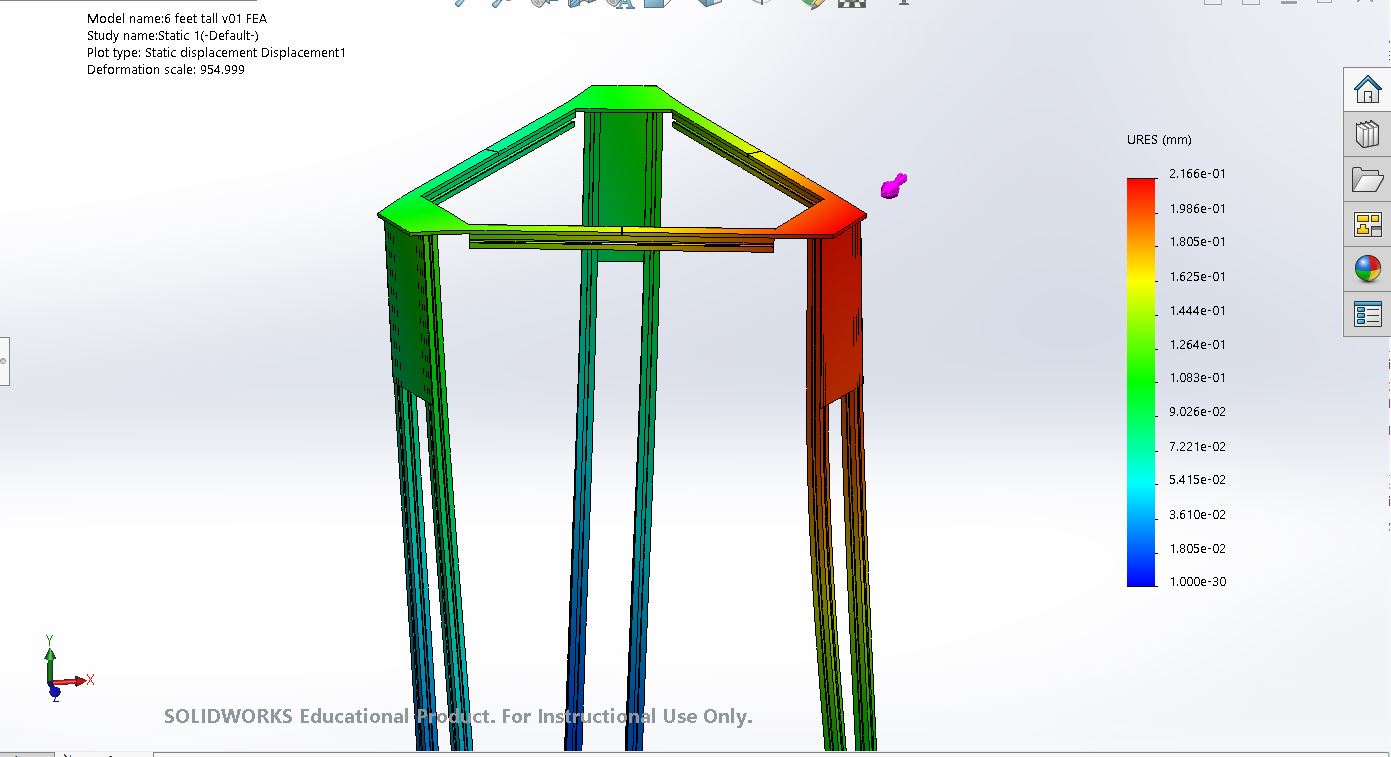
After completing the assembly, we decided to add more supporting structure to the main frame in order to make the printer more stable. To find out what structure does the best job, we created a simplified model in SolidWorks and ran some preliminary FEA analysis on the structure coupled with different support structures. For each scenarios, we added both torsional and horizontal load for a more well-rounded evaluation.

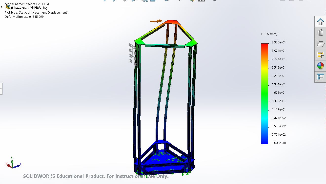
FEA results - original design
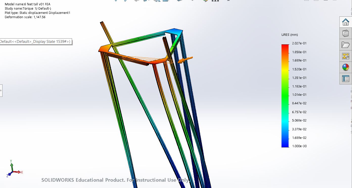
FEA results - long cross beam on the side
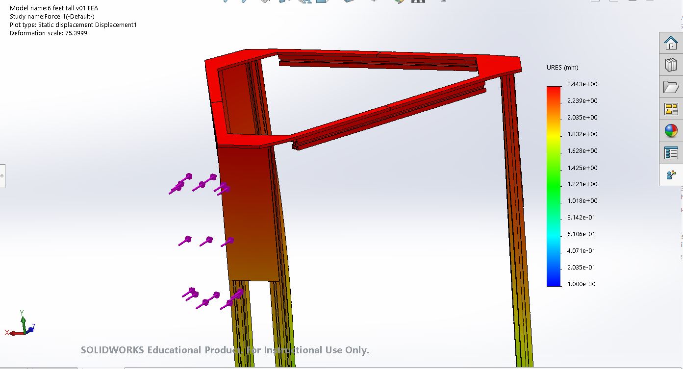
FEA results - side panel on the top
The Design
I started by making some preliminary sketches on my iPad. One of the largest issues we have on the small ceramics printer is that if the power is cut off or a soft reset is triggered, the motors will be allowed to spin almost freely; with the weight of the extruder filled with clay, the print head will fall and hit on the unfinished print on the build plate. So after some thought I decided to replace the timing belt with a long lead screw.
I also decided to build the main frame with 8020 aluminum extrusions and 6061 aluminum plates made by online waterjet services. Here's a link to the bill of materials I created that are still under minor revisions.
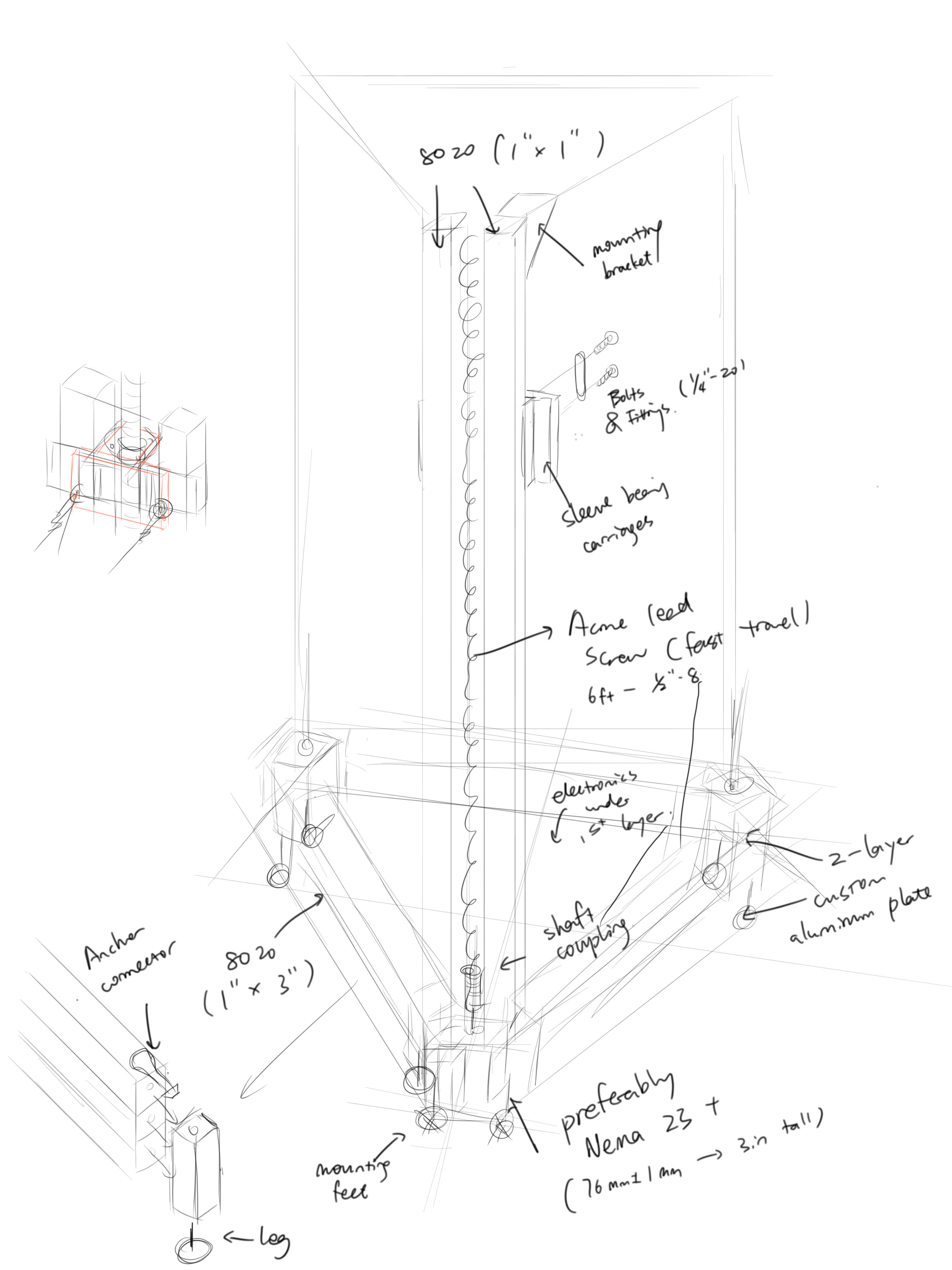
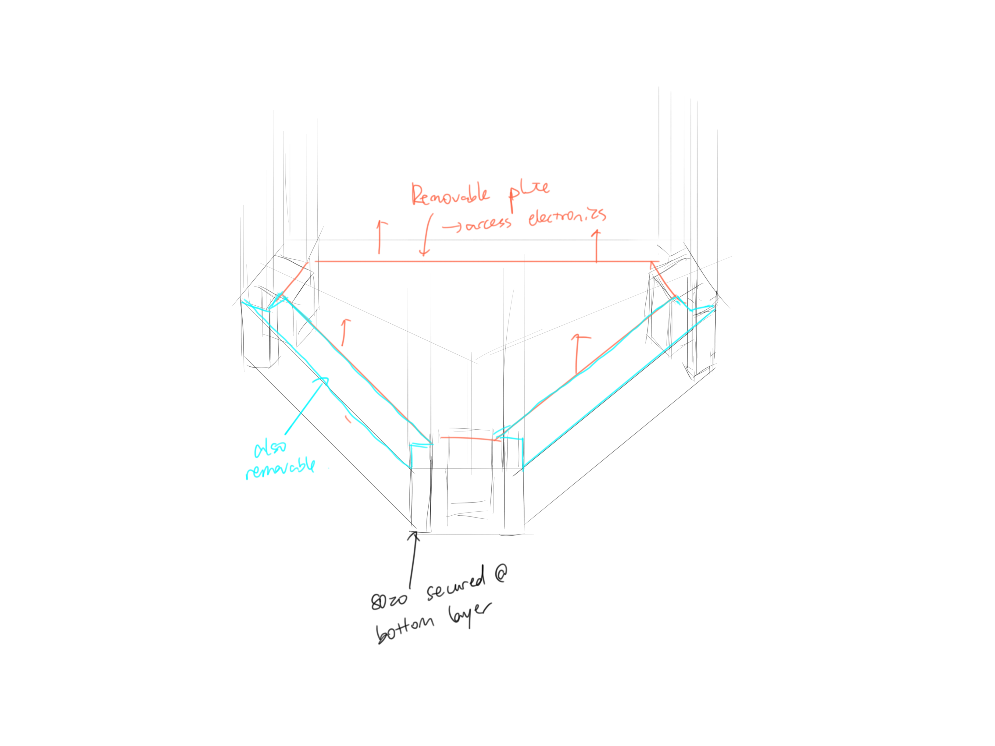
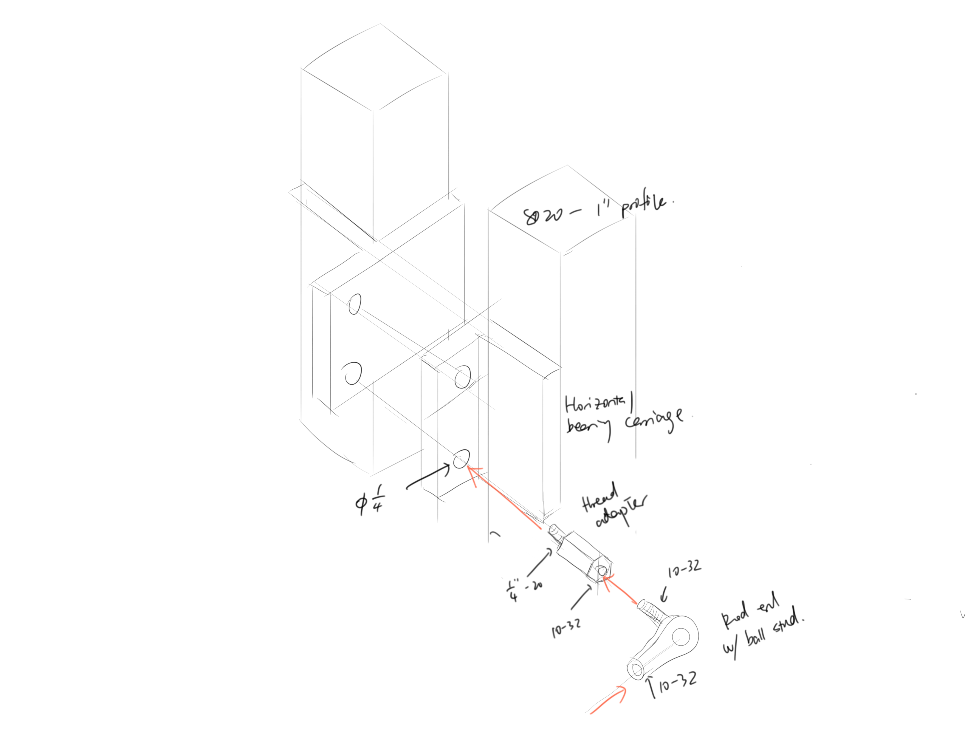
Design sketches
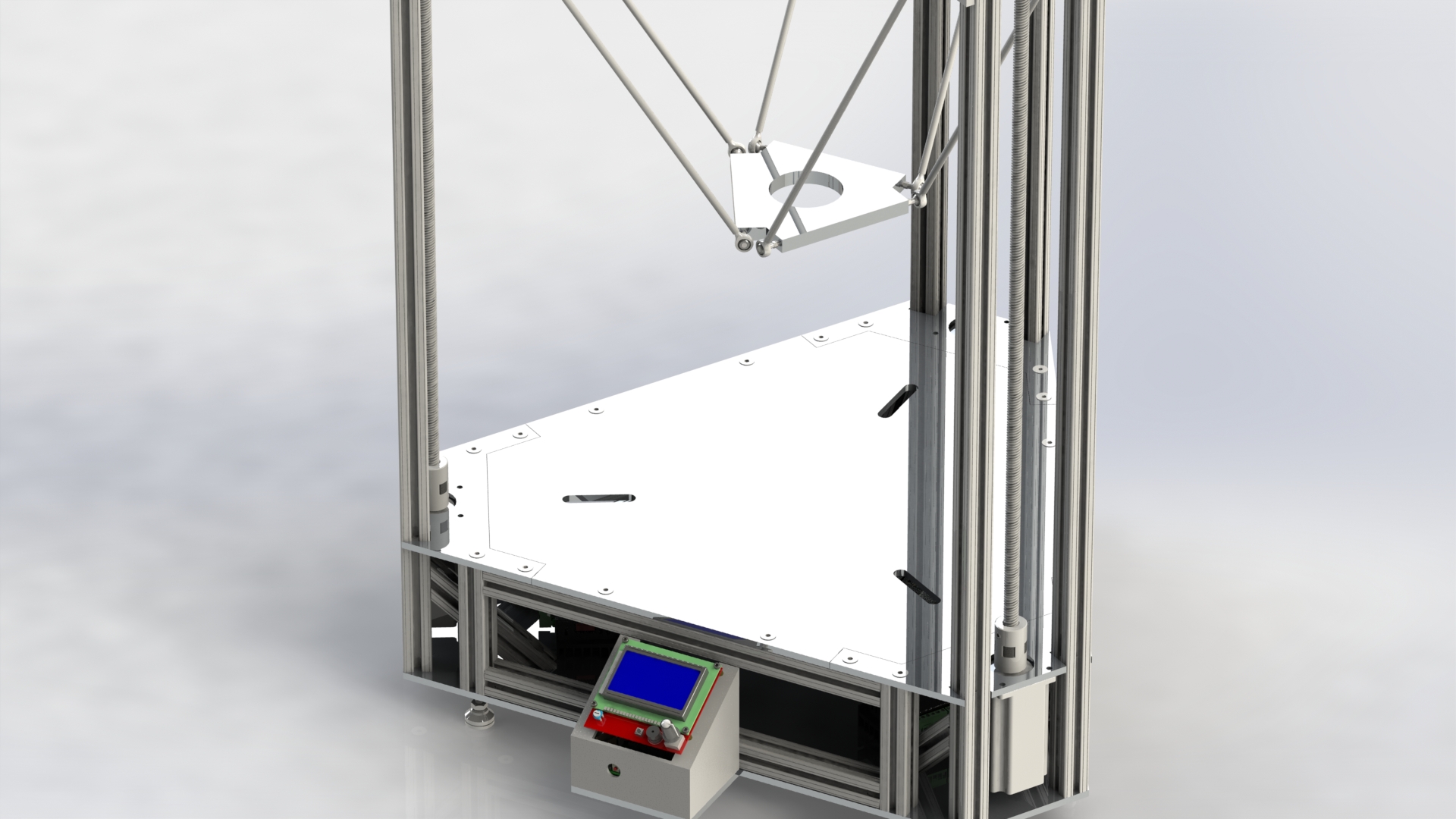
CAD renderings
Initial Fabrication
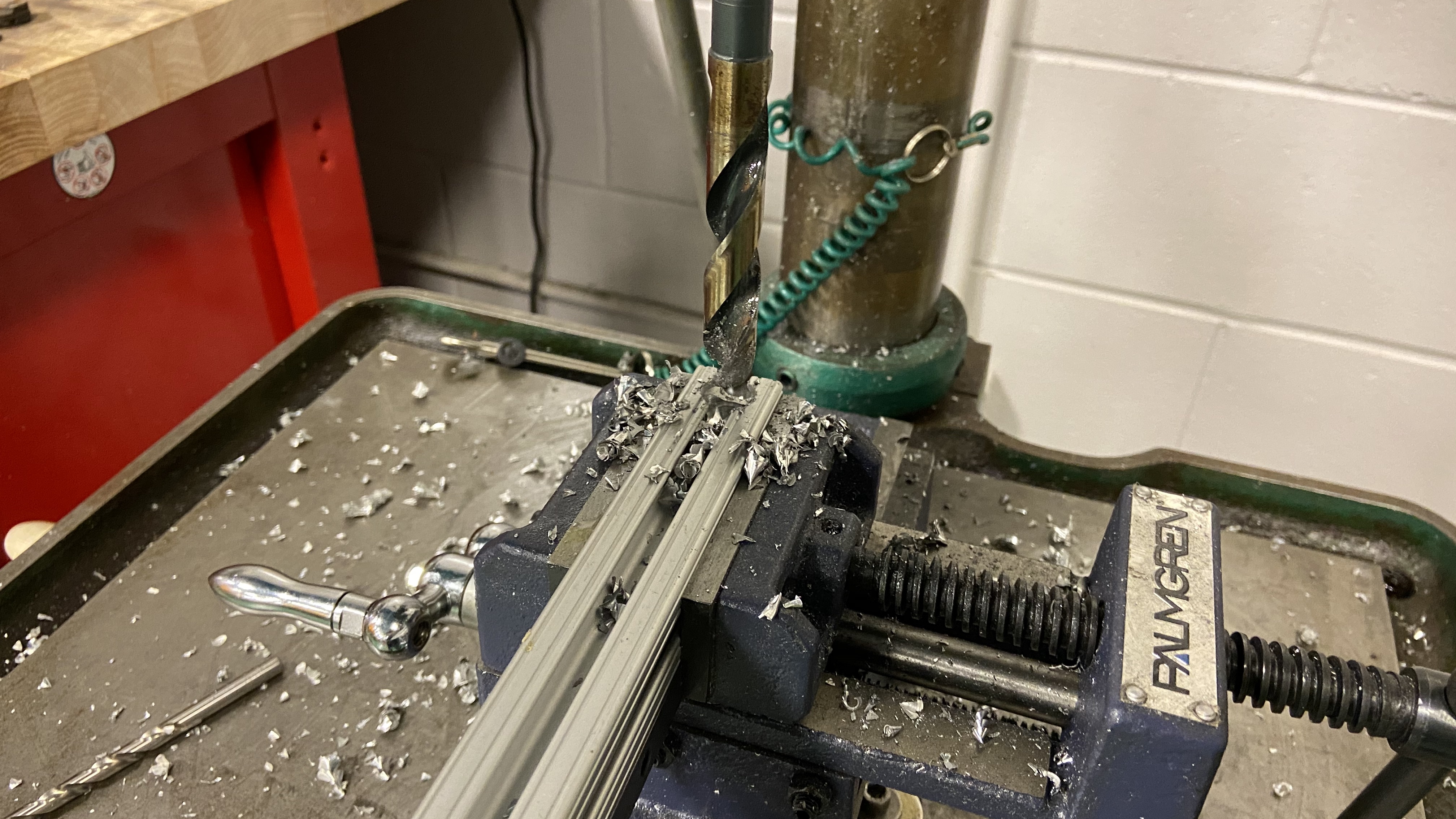
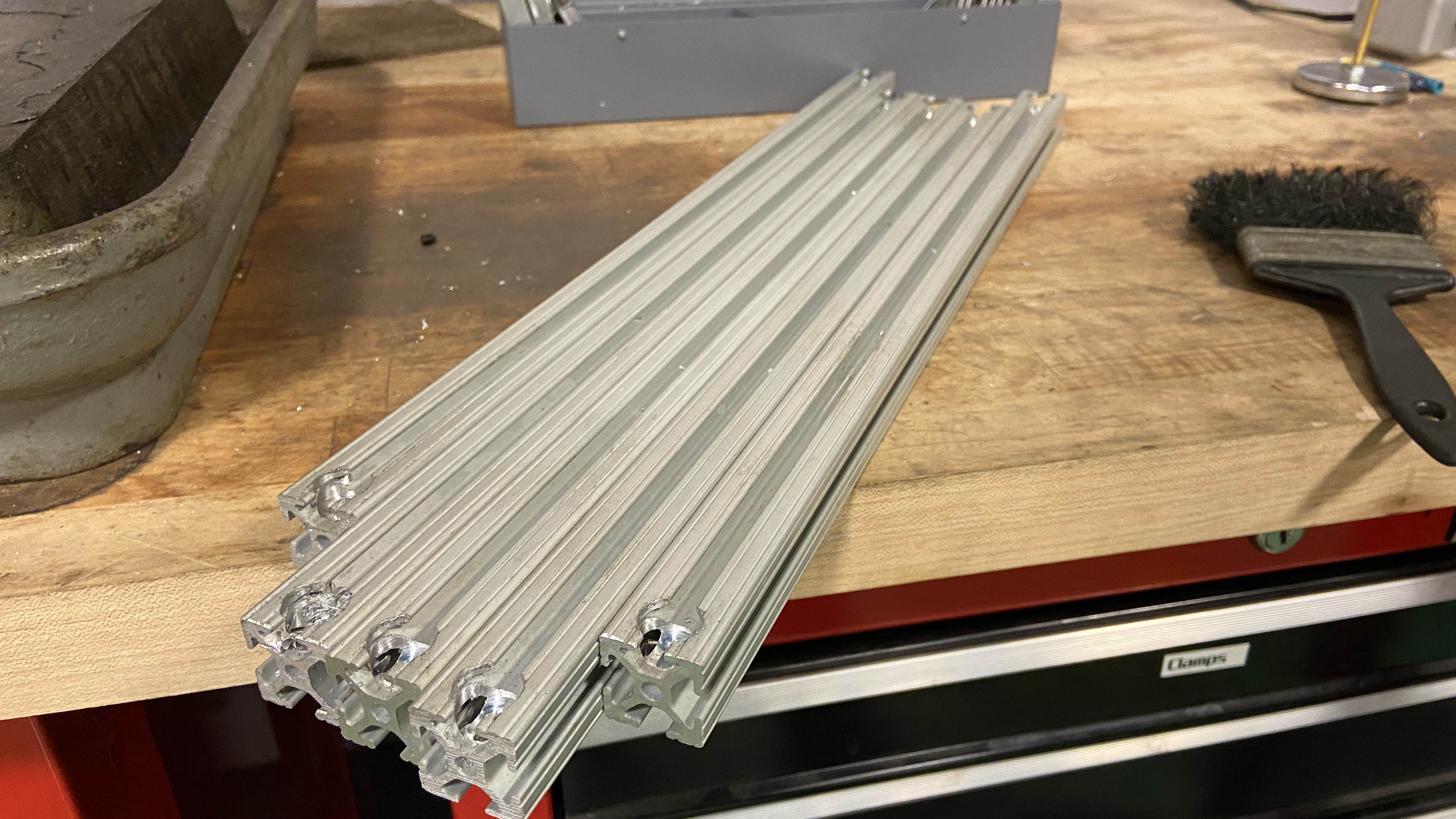
To reduce the overall cost, we ordered 6 feet 8020 aluminum extrusions and machined them to desired conditions ourselves. Mainly, we used the band saw to cut the horizontal and vertical short pieces, drilled large holes on the side for the anchor connectors, and tapped the ends of the rails with 1/4''-20 keys.
Single Axis Test
Partial tests are a necessary step in the prototyping process. Therefore, I quickly assembled a small portion of the printer's mechanical structure - a single axis with one lead screw mounted with one NEMA 23 Motor. I uploaded the Marlin firmware to the electronics board, wired up one-third of the printer, and did some quick calibration tests to make sure the mechanical design is working. I also tested the motor's strength by attaching appropriate weights to the axis (about half of the expected load, which in the final design will be split between 3 identical axis). Based on the initial test, the design proved to satisfy out requirements.
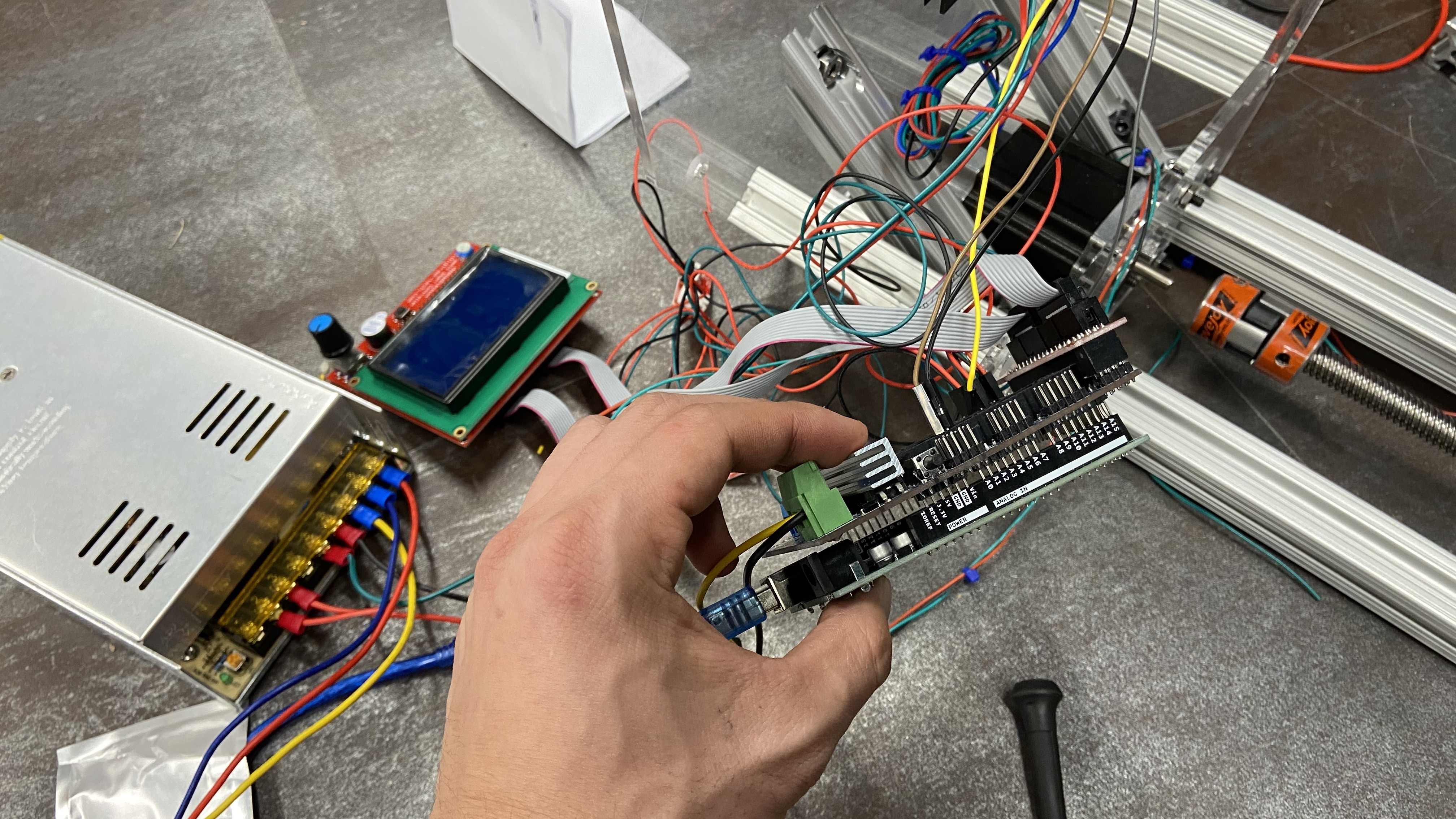
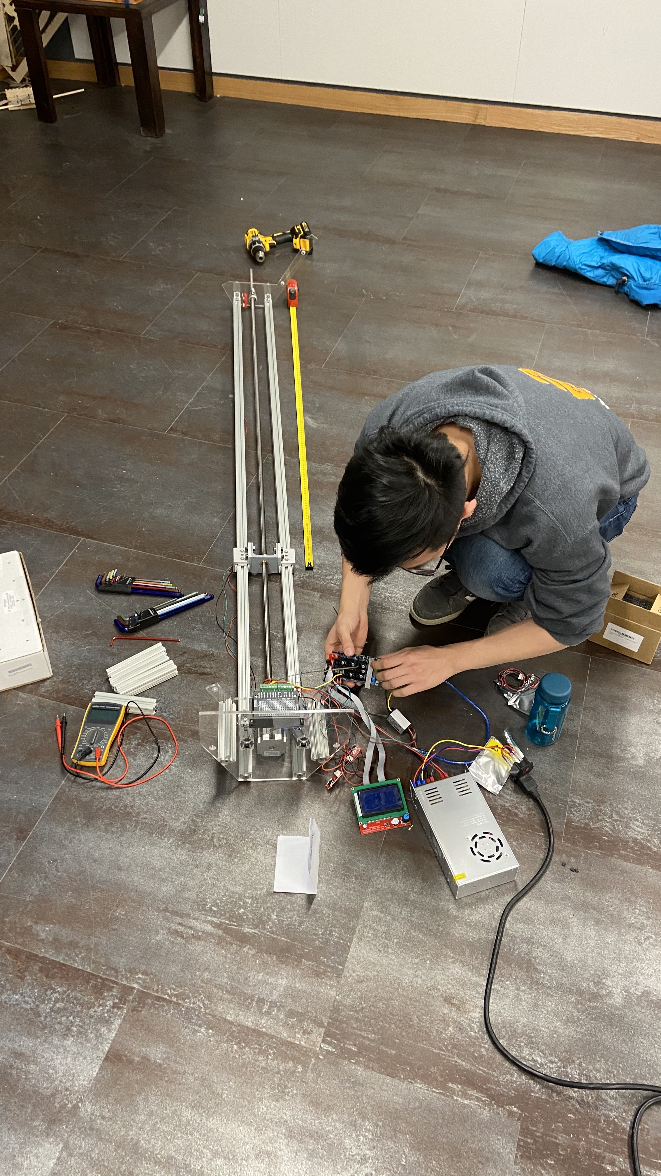
Initial load test
Assembly Test
We recently assembled the main structure for the first time. We have not yet placed the orders for the aluminum plates, and are substituting the aluminum plates with laser-cut plywood of the same thickness as temporary placeholders. This way we can double-check to make sure that the design does not have any major flaws when we place the big money order for custom fabrication.

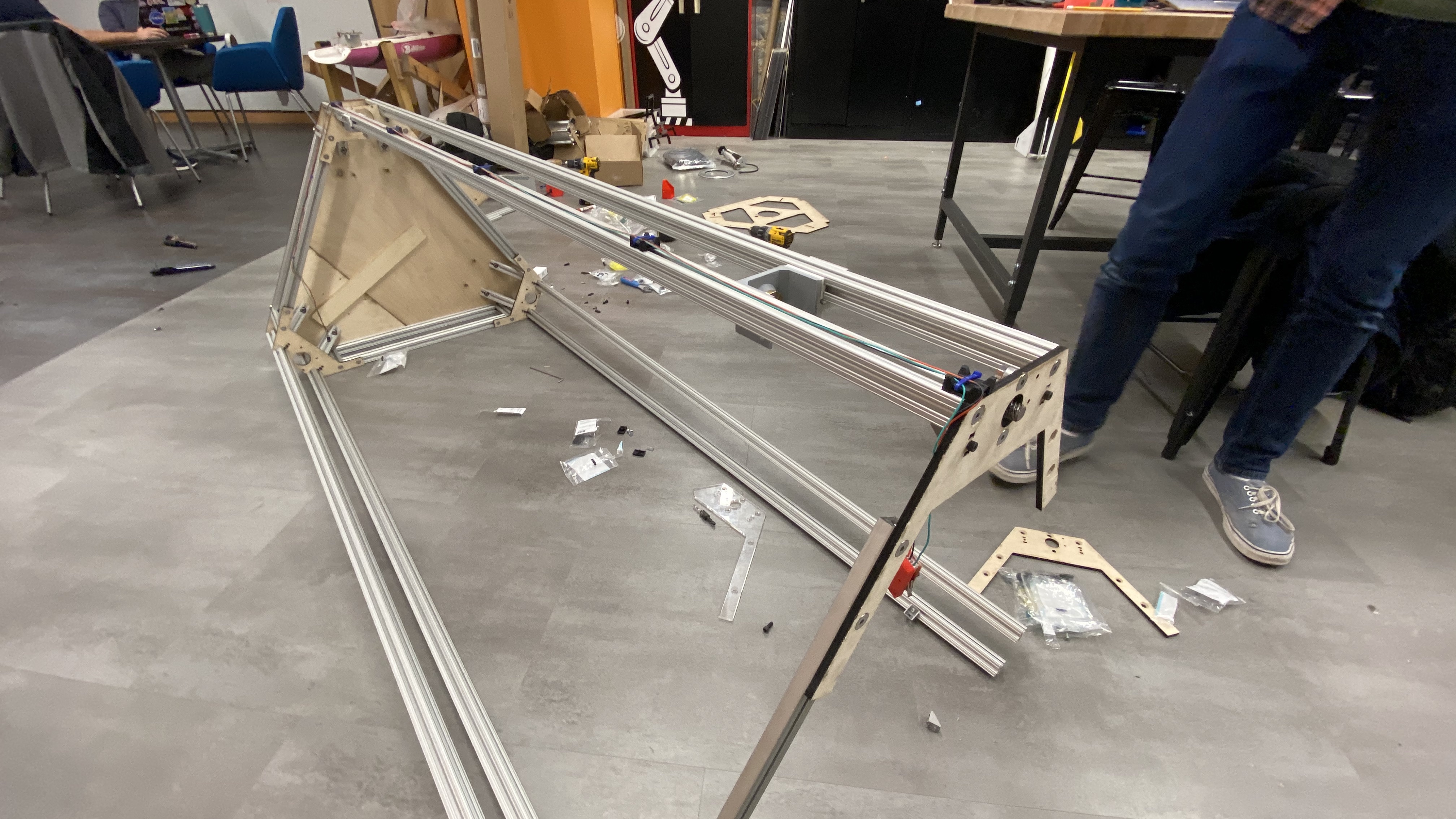
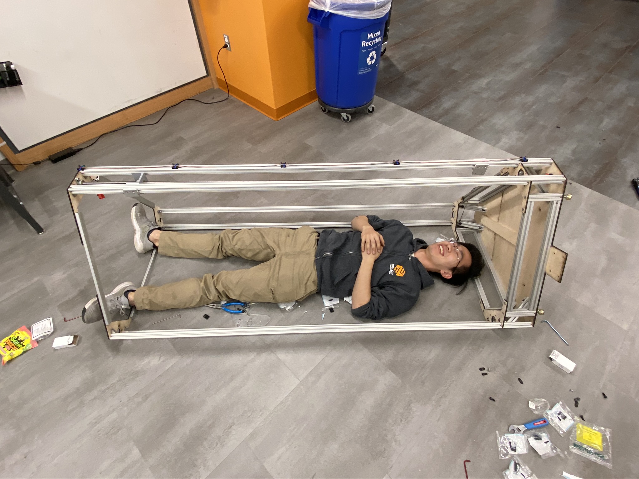
As a comparison, my height is about 5'8'' :)