Fluidic Control Board
One of the key components of soft robotics research is to have a systematic way to test and deploy soft actuators. Starting in summer 2019, I built a fluidic control board for pneumatic actuators by following an open-source instruction on the Soft Robotics Toolkit website. Later in the process, I built my own adaptation of the open-source design with a few improvements.
Following Instructions
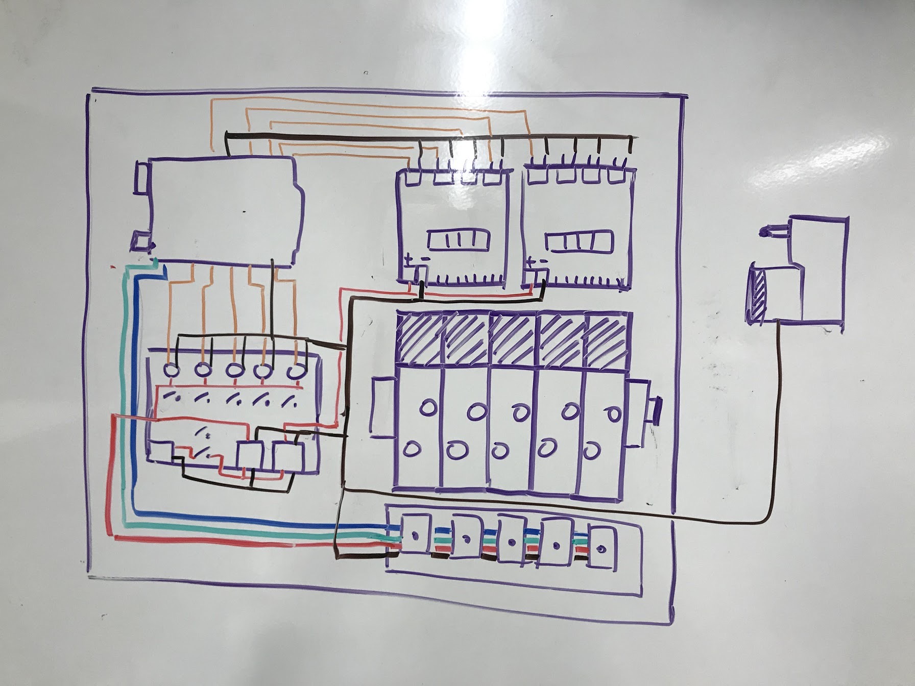
I reviewed the old bill of materials from the website and ordered the key components. One of the modifications I made was that I replaced the industrial solenoid valve manifold apparatus with a cheaper substitute from Amazon. With all the components on hand, I followed the wiring instruction from the original design, but assembled the components in a more optimized placement plan.
Control board working with a custom air muscle made in the lab

Building process
While building the first version, I encountered several challenges. One of them was that the solenoid valves I purchased has a higher minimum operating pressure that makes it compatible with the miniature air pump that came with the original design, forcing me to use a heavy-duty air compressor instead. This was mainly resulting from my lack of background knowledge in solenoid valves as I was sourcing materials, and has taught me a valuable lesson to always double-check with the specs of the materials before I make any purchase.
Making My own Version
After I got familiar with the components and working principle of the original control board, I decided to make my own version with a complete mechanical redesign and replacements of some components.
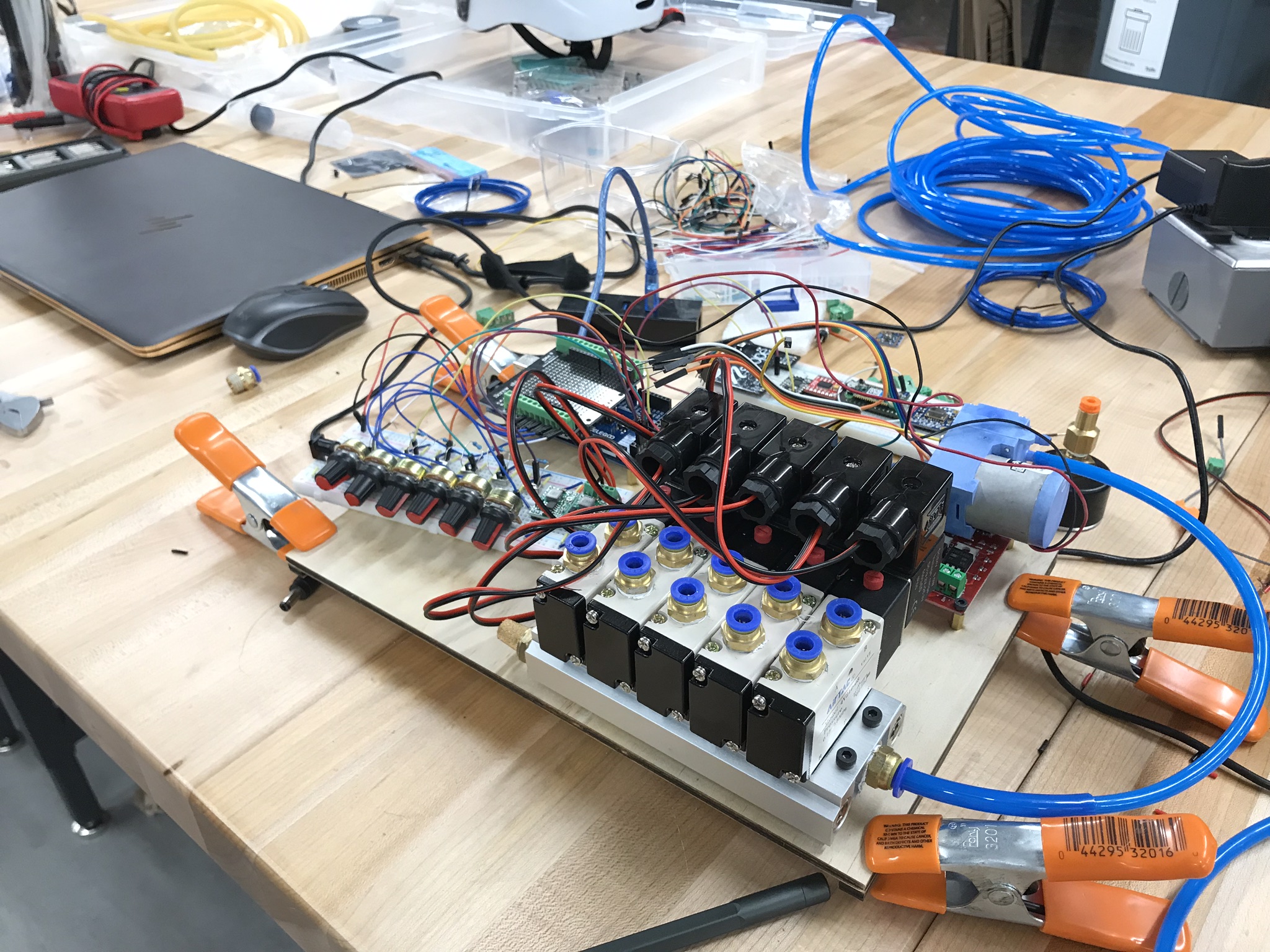
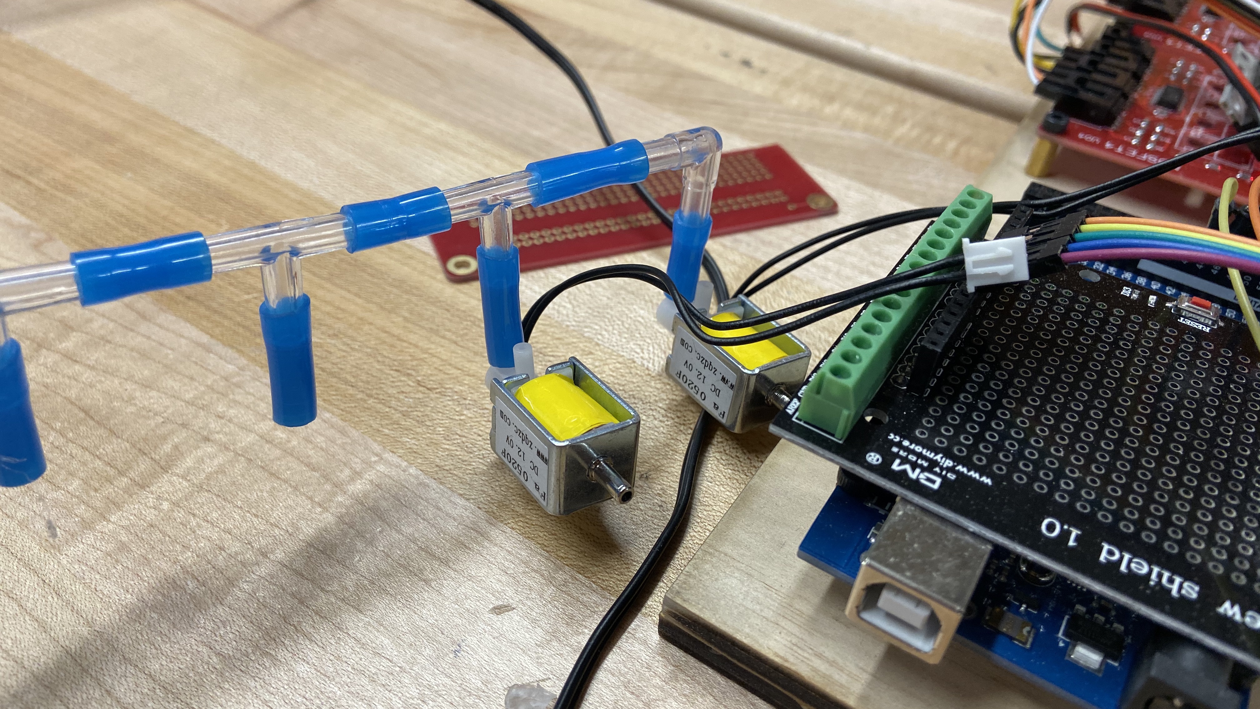
Firstly, I replaced the clumsy solenoid valves with some miniature, 3 way 2 positions solenoid valve which is compatible with the miniature industrial air pump. These mini valves could not stand high pressure applications as well as the previous ones, but considering that most of the actuators designed in my lab are small-scale, compliant PneuNet bending actuators, the mini valves are enough for the job.
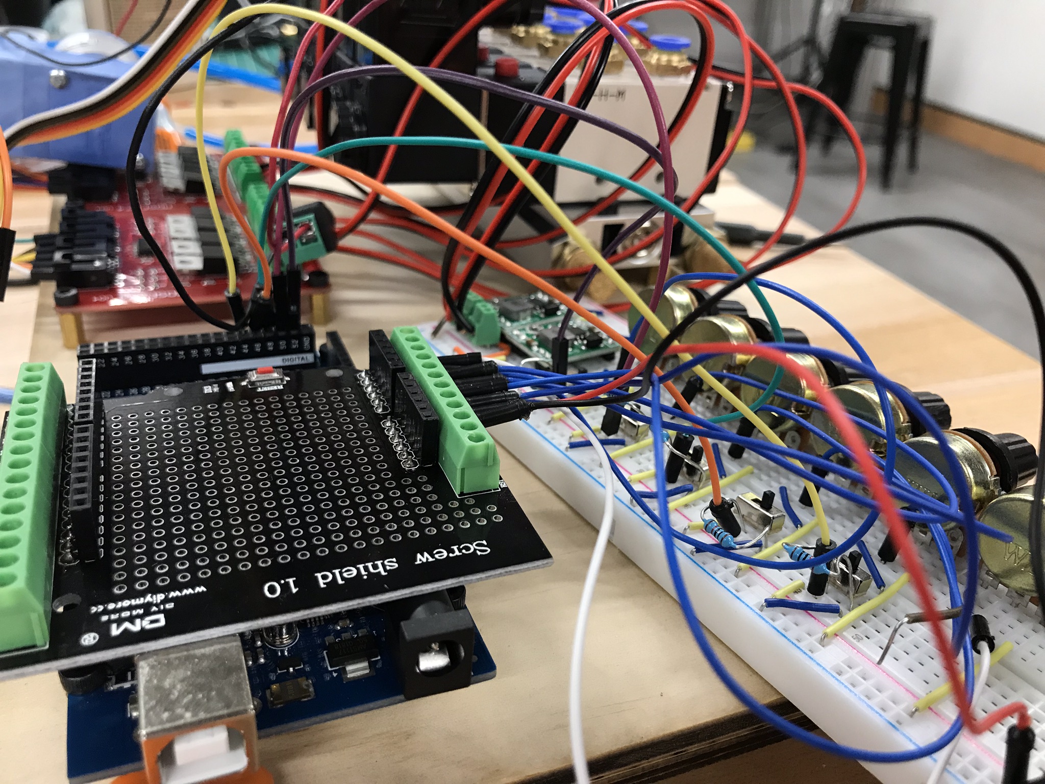
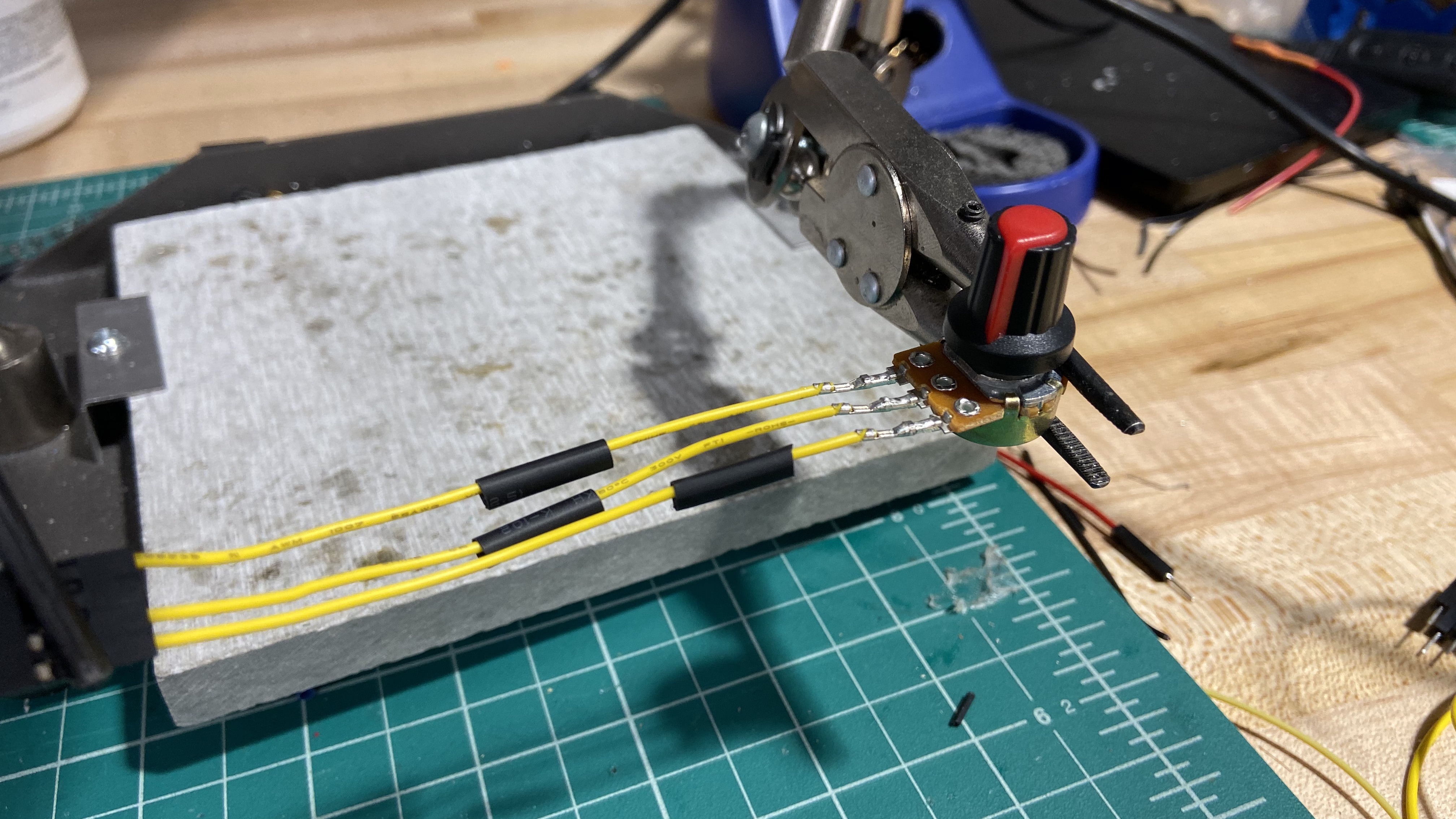
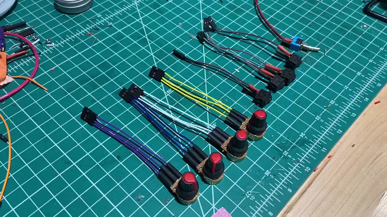
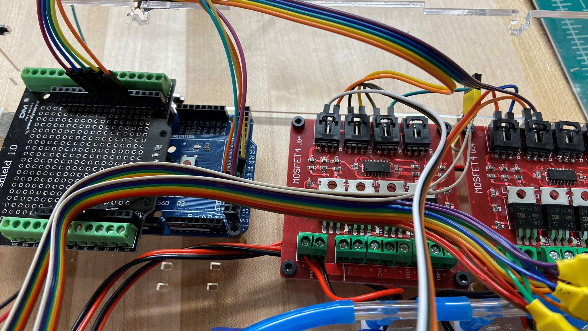
Second, I designed my own wire management system and put most of the connections onto a half-size solderable breadboard as a semi-permanent solution. I also made custom Dupont wires to connect the switches, potentiometers, and the MOSFET boards.

Lastly, I designed a laser-cut clear acrylic fixture as enclosure to house everything in a compact way. This also makes it easier for everyone to see the operation in detail and helps debugging if necessary.
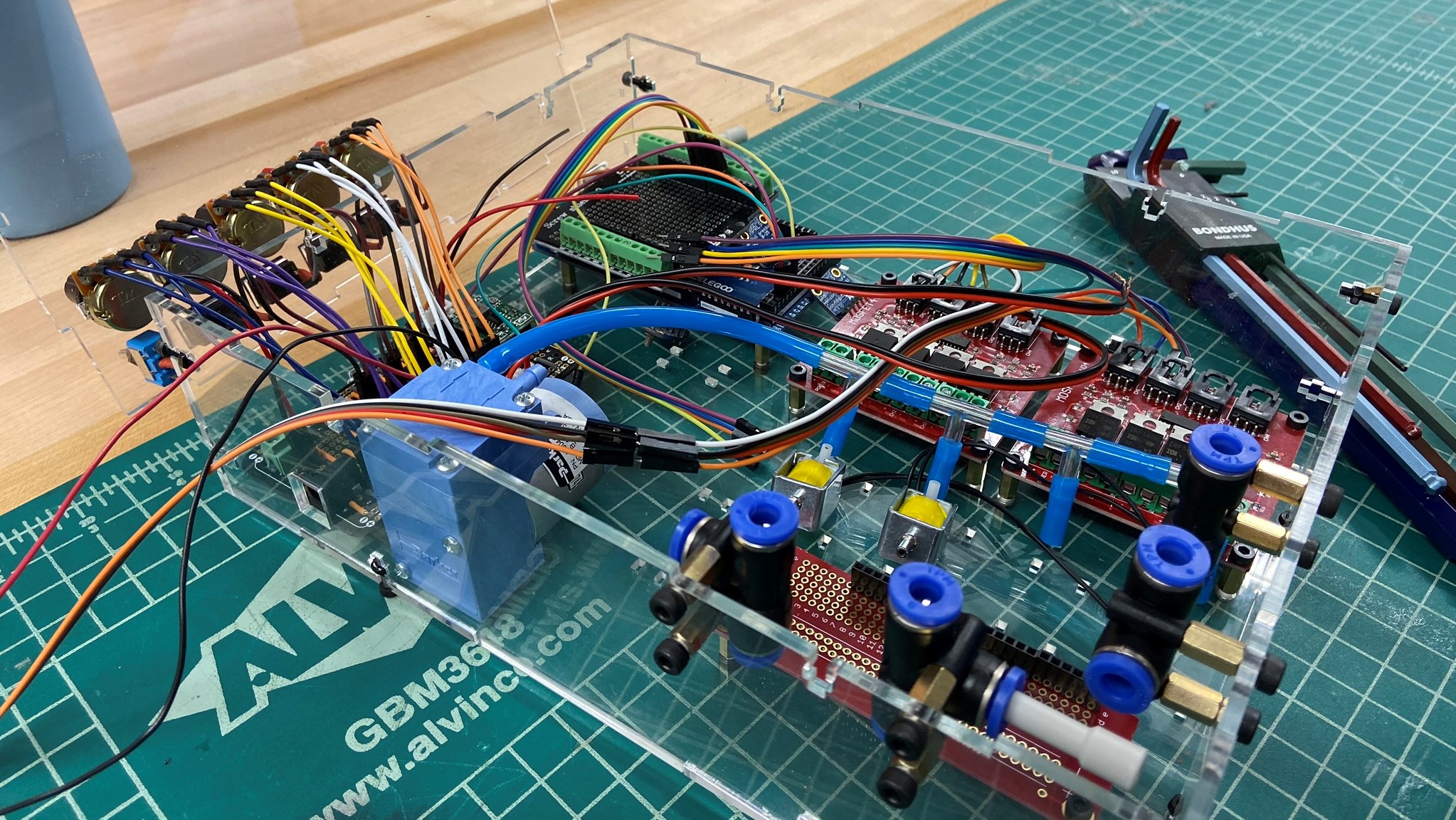
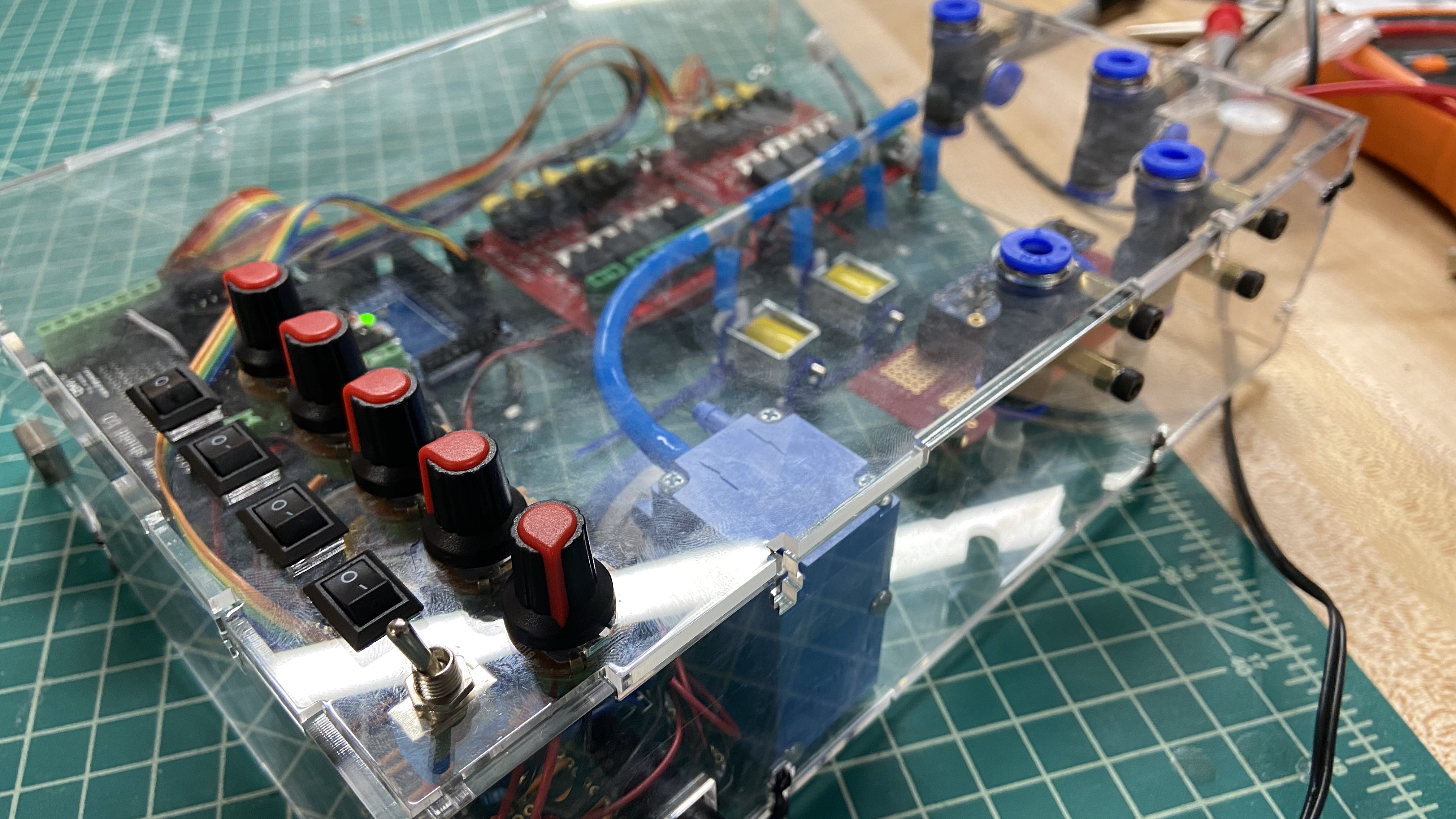
Control board test